Rigid Circuit Board (PCB)
-
Supplier Type: PCB Fabrication
-
Layers: 10L
-
Plate thlCkness: 1.6mm
-
Minimum aperture: 0.296mm
-
Line width: 0.342*0.37mm
-
Size: 43.68*38.9mm
- No MOQ or MPQ limited.
- Daily quotes and negotiations.
- Prototypes quotation within 3h.
- Flexible payment options.
- Prototype or mass production order acceptable.
-
Project Info
-
Specification
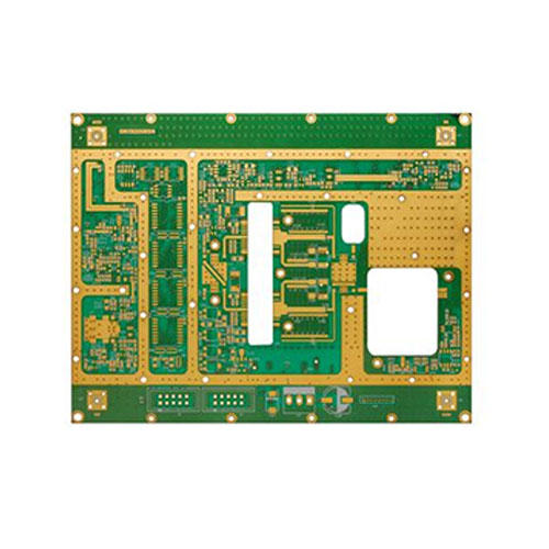
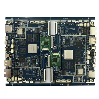
What is a Rigid Circuit Board (PCB)?
A rigid circuit board (PCB) is a flat, rigid board that houses electrical components. A thin layer of copper foil is layered between two thin layers of fiberglass or other dielectric material. This sort of board is used to link electrical components in a single unit, such as resistors, capacitors, and transistors. This enables the components to be connected in a precise and repeatable manner.
The primary advantage of rigid circuit boards is their stiffness. This helps to guarantee that the components are connected in a consistent and trustworthy manner, and it also decreases the possibility of a defective connection. Furthermore, the rigid architecture of the board allows for a significantly denser component layout, which can help to reduce the total size of the system.
Flexible printed circuit boards, for example, are far more difficult to deal with than rigid circuit boards. This is because they are less prone to warping or cracking and are considerably easier to solder and desolder.
Benefits of Rigid Circuit Board (PCB)
Rigid circuit boards have several features that make them excellent for a variety of applications. First and foremost, they are incredibly dependable and long-lasting. This makes them ideal for use in mission-critical systems, where even little errors can have disastrous implications. They are also very resistant to vibrations and temperature variations, making them excellent for usage in harsh locations.
Rigid circuit boards are also quite flexible. They can be made in virtually any shape or size, and they can be tailored to the precise requirements of any application. They are also reasonably simple to work with, making them an excellent choice for prototyping and testing.
Finally, rigid circuit boards may be mass-produced in large quantities at a low cost. When compared to other types of circuit boards, this makes them incredibly cost-effective.
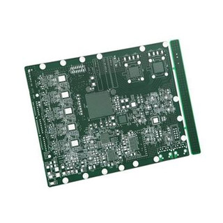
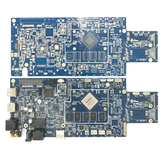
Different types of Rigid Circuit Board (PCB)
Rigid circuit boards are available in a variety of shapes and sizes. A single-sided board is the most common form, with a single layer of copper foil on one side. Because it can readily contain a modest number of components, this sort of board is suitable for simple circuits.
Double-sided boards with two layers of copper foil are also available. These boards are more sophisticated because they can hold a greater number of components. Furthermore, they can provide far more sophisticated circuitry.
Multi-layer boards with numerous layers of copper foil are also available. These boards are exceedingly complicated, and their production requires specialist equipment. They can, nevertheless, provide unprecedented levels of performance, making them perfect for the most demanding applications.
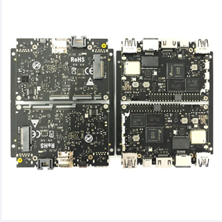
Applications of Rigid Circuit Board (PCB)
Rigid circuit boards are utilized in a variety of applications, including consumer electronics and aeronautical equipment. They are especially well-suited for usage in mission-critical systems, where dependability and durability are important. They are also widely utilized in automobile systems, communications systems, and medical devices.
Designing Rigid Circuit Board (PCB)
Creating a rigid circuit board can be a difficult and time-consuming task. It necessitates a deep understanding of electronics as well as an attention to detail. Furthermore, it is critical to understand the various materials and components that might be employed in the board, as well as the application’s special needs.
Making a schematic diagram is the initial stage in designing a rigid circuit board. This diagram should include all of the board’s components as well as the connections between them. It should also mention any additional components that may be required for the board to perform properly.
When the schematic is finished, it is time to design the board layout. This includes deciding where to put all of the components and how to route the traces. Furthermore, it is critical to pay great attention to the component tolerances, as this might have a considerable impact on the board’s performance.
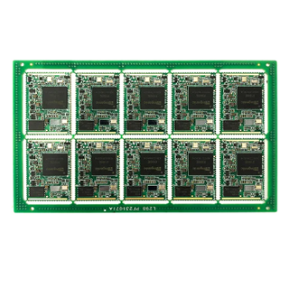
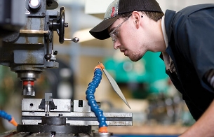
Production of Rigid Circuit Board (PCB)
After the board has been created, it is time to begin production. This stage entails converting the design into a real board. This is typically accomplished through the use of photolithography, which entails etching the copper traces onto the board. Furthermore, components such as resistors and capacitors must be attached to the board.
The manufacturing process might be complicated, and the board must be made to the highest standards. It is also critical to choose high-quality components to guarantee that the board functions properly. Furthermore, before the board is put out for use, it must be thoroughly tested.
Manufacturing Considerations for Rigid Circuit Board (PCB)
Making rigid circuit boards can be a time-consuming and expensive process. As a result, a number of criteria must be addressed to ensure that the board is of the highest quality. This includes deciding on the right board material, such as FR4 or polyimide, as well as the right board components. The layout of the board and the routing of the traces must also be considered.
The manufacturing process must also be considered. This includes selecting the necessary tools and equipment, as well as the methods that will ensure the board is created effectively and accurately. Furthermore, the board’s quality must be evaluated, as this can have an impact.
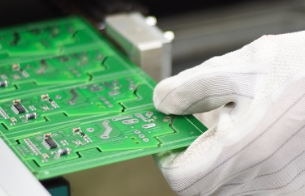
Testing Rigid Circuit Board (PCB)
Once the board has been produced, it must be properly tested to ensure that it operates as planned. This includes checking the board for electrical and mechanical problems, as well as making sure the components are properly soldered. It is also critical to test the board for electrical noise and electromagnetic interference.
The testing process can be time-consuming and complex, so having the necessary tools and equipment is critical to ensuring that the board is tested correctly. Furthermore, a detailed understanding of the board as well as the testing process is required.
Troubleshooting Rigid Circuit Board (PCB)
In some circumstances, troubleshooting a rigid circuit board may be required to discover and resolve any difficulties. This procedure often includes inspecting the board for apparent flaws such as damaged components or incorrect connections. It is also critical to inspect the board for any parasitic elements, such as stray capacitance or inductance.
It is also critical to inspect the board for any electrical problems, such as shorts or leaks. It is also critical to inspect the board for any interference from outside sources, such as radio waves or magnetic fields. Finally, it is critical to inspect the board for any other faults that could impair its functioning.
Conclusion
Rigid circuit boards have many advantages over other types of circuit boards, making them perfect for many applications. They are incredibly dependable and long-lasting, and they may deliver exceptional levels of performance. They are also reasonably straightforward to deal with and may be produced in large quantities at a reasonable cost.
Rigid circuit boards are an excellent alternative for building sophisticated electrical components and gadgets since they are both efficient and dependable. You can produce high-performance and reliable boards that will endure the test of time if you have a full understanding of their design and manufacturing processes.
So, if you’re ready to discover the delights of rigid circuit boards, now is the time to begin! The possibilities are limitless, whether you’re a beginner or an expert. So get out there and start making things!
Basic introduction
| Name: | 10-layer PCB circuit board |
| Layers: | 10L |
| Application | Automotive industry, Power supplies and power converters, Welding equipment |
| Electrical Testing | Fixture / Flying Probe |
| Quality Grade | Ipc Class 2, Ipc Class 3 |
| Silkscreen Colors | Red Oil/Green/Blue/Black/White |
| Other Testing | Aoi, X-ray(Au&Ni), Controlled Impedance Test |
| Placement speed: | Chip component placement speed (at best conditions) 0.036 S/piece |
| Surface Finishes | Immersion Gold, OSP, and HASL |

Our 2 Layer PCB Board Features
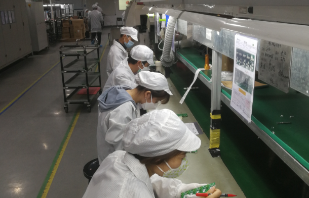
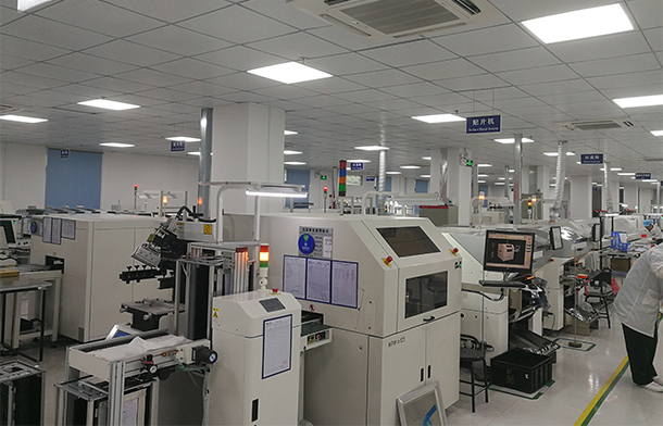
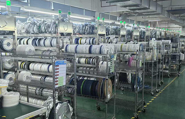
Our PCB Factory Tour


Why choose us for PCB assembly services
Economy
We can provide various types of PCB boards and various materials at competitive prices according to customer requirements.
Best Team
No Matter What Kind Of Pcb Board You Want, Our Trained Designers Can Make lt lnAbout 10-12 Working Days. Emplovees Know The lmportance Of Deadlines, AndTheir Goal ls To Give You Top-Notch Results Within A Specified Time Frame.
Best Team
No Matter What Kind Of Pcb Board You Want, Our Trained Designers Can Make lt lnAbout 10-12 Working Days. Emplovees Know The lmportance Of Deadlines, AndTheir Goal ls To Give You Top-Notch Results Within A Specified Time Frame.
Service
Brnon co0p PchaSn To Functes Candackage Finish , We Provid